Document details
8
1
T. Flohrer, S. Lemmens, F. Schmitz

Abstract
1 INTRODUCTION
One of the major difficulties to achieve active debris removal is rendezvous to a target debris on-orbit. Unlike cooperative target, such as ISS, debris has no markers which enables chaser’s relative navigation. LiDAR is one of the candidate sensors for relative navigation against the target debris. In general, LiDAR emits laser light and measure the reflection with a detector to measure a round trip time, which can be converted to distance. This feature enables chaser to obtain the distance from target without onboard image processing which is necessary for optical cameras. Therefore, it is demanded to develop a space-grad LiDAR for debris removal missions.
However, it has difficulty testing LiDAR on ground for following reasons:
1. General relative sensors, typically for automobiles, are evaluated by experiment on ground and have chance to calibrate to optimize its performance, while sensors for space have no chance to feedback the experimental results after its launch
2. Usually sensors for space are evaluated on ground with various conditions simulating all the possible cases in the space
3. Unlike optical cameras, full-scale model is necessary for evaluation because distance error is also scaled if LiDAR is evaluated by sub-scale model
4. Full-scale model is too large if the target debris is used rocket body or un-operational satellite.
For these reasons, our goal of this research is defined to simulate LiDAR measurement data as precise as possible to realize evaluating LiDAR navigation performance with various conditions.
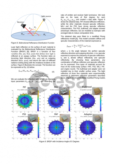
As LiDAR measures distance by observing reflection laser light from the target, reflection on target surface is one of the key factors. In addition, measurement errors have a correlation to reflection intensity. For these reasons, light reflection intensity of debris’ major surface materials is experimentally obtained and Bidirectional Reflectance Distribution Function (BRDF) model is adopted for emulating laser light reflection.
2 REFLECTION MODEL
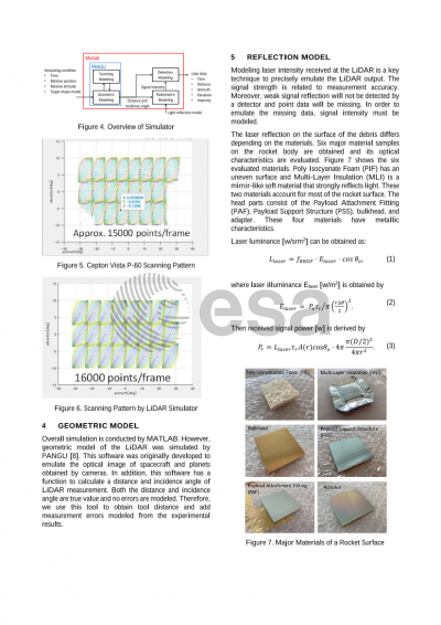
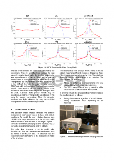
Laser light reflected on the surface of the debris is modelled by modified Phong reflectance model. This model considers a diffuse and a specular characteristic of the material. By choosing appropriate parameters, any combination of diffuse reflection and specular reflection can be expressed. Five types of materials account for majority of the rocket body surface: Payload attachment fitting (PAF), payload support structure, polyisocyanurate foam, multi-layer insulation, and engine nozzle. The light reflection of those five materials are experimentally observed and reflection parameters explained above were decided. The simulator emulates the laser light reflection using the modified Phong model with each material parameters.
3 SIMULATOR EVALUATION
A rocket booster was chosen as target of removal because rocket bodies account for large portion of the debris on orbit and rocket bodies have a similar outlook compared to other space debris. If we could realize removing a rocket body from orbit, it is easy to extend its technique to remove another rocket debris. Therefore, we firstly realized to emulate LiDAR output of a rocket body observation.
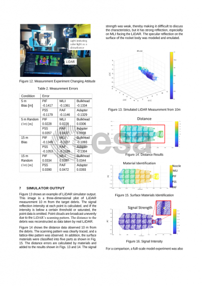
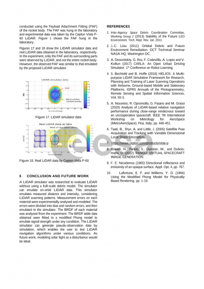
In the full paper, various conditions of example outputs by LiDAR simulator are introduced. Signal reflection intensity at each point is calculated and if the intensity is below a certain threshold or saturated, the point data is omitted. Point cloud is broadcasted unevenly due to LiDAR’s scanning pattern. The distance to the debris was reconstructed as a data taken by real LiDAR.
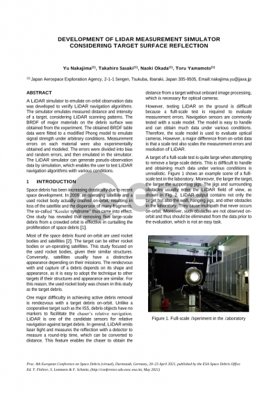
For a comparison, a full-scale model experiment was also conducted using Payload Attachment Fitting (PAF) of rocket body. PAF was hanged in the laboratory and experimental data is taken by Cepton Vista P-60 LiDAR. Obtained data was compared to the simulator data facing PAF of the rocket body model.
Preview